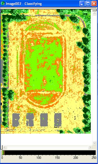
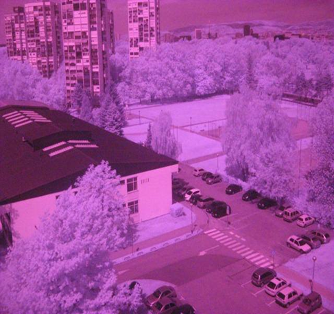
During the summer semester students attending the Aerial Reconnaissance and Surveillance course at the Department of Aeronautics partake in a student project designed to push their planning, design, and problem-solving skills to their limits. This year, the task was to produce and analyse aerial infrared imagery of one part of the University Campus using very limited funds.
The project was presented to the students as a fictitious EU-funded Call for Project Proposals. Students had to read the Call, analyze the requirements, devise a solution, and submit a formal project proposal covering all aspects of project management such as: plan of activities, schedule, budget, SWOT analysis etc.
One caveat was that the proposal had to include usage of additive manufacturing technologies (3D printing). The students were split into two groups, each writing their own project proposal. The group led by Mr. Josip Kovač-Levantin won the grant and afterwards two groups merged to continue working on the winning proposal together.
Three main work packages were defined: designing and printing the airframe, assembling and programming the electronics, and modifying the common digital camera to serve as an infrared sensor.
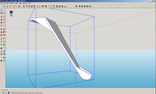
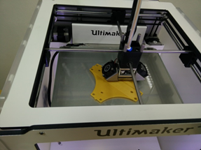
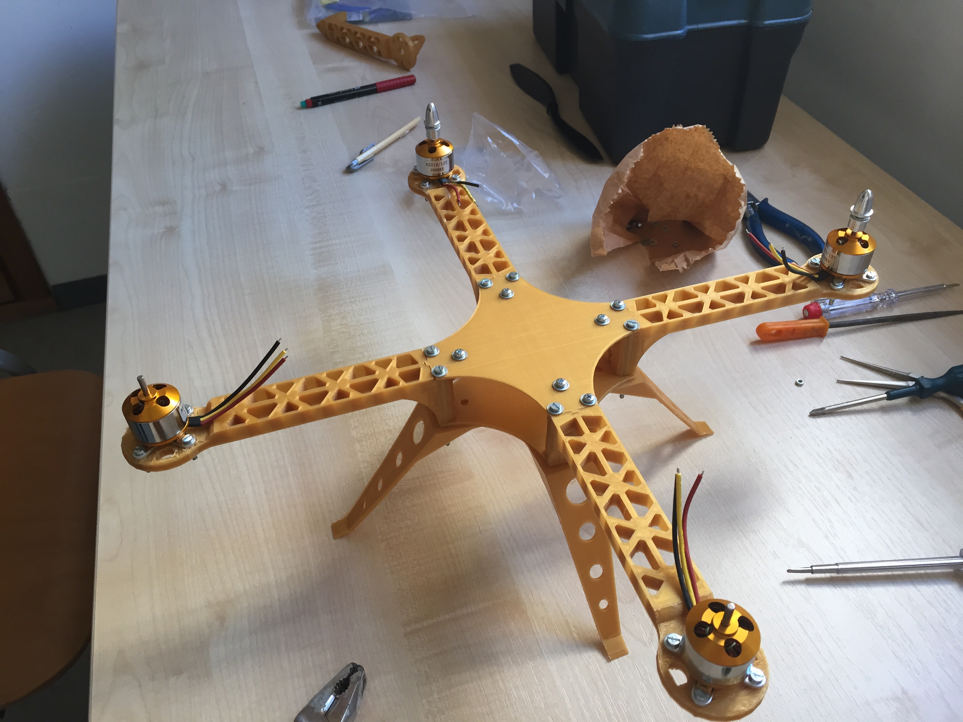
Design of the airframe was done in SketchUp , then transferred to Cura for conversion into printer-friendly format, and finally printed on the Ultimaker 2 3D printer with PLA filament. Additive manufacturing is currently certainly not the least expensive option when it comes to building an airframe for the aerial vehicle, however, it allowed rapid prototyping and redesigning of the airframe. PLA filament is also not the strongest and lightest material for building the airframe. On numerous occasions the frame broke on hard landings (read: crashes) but upside was that the required spare parts could be produced swiftly.
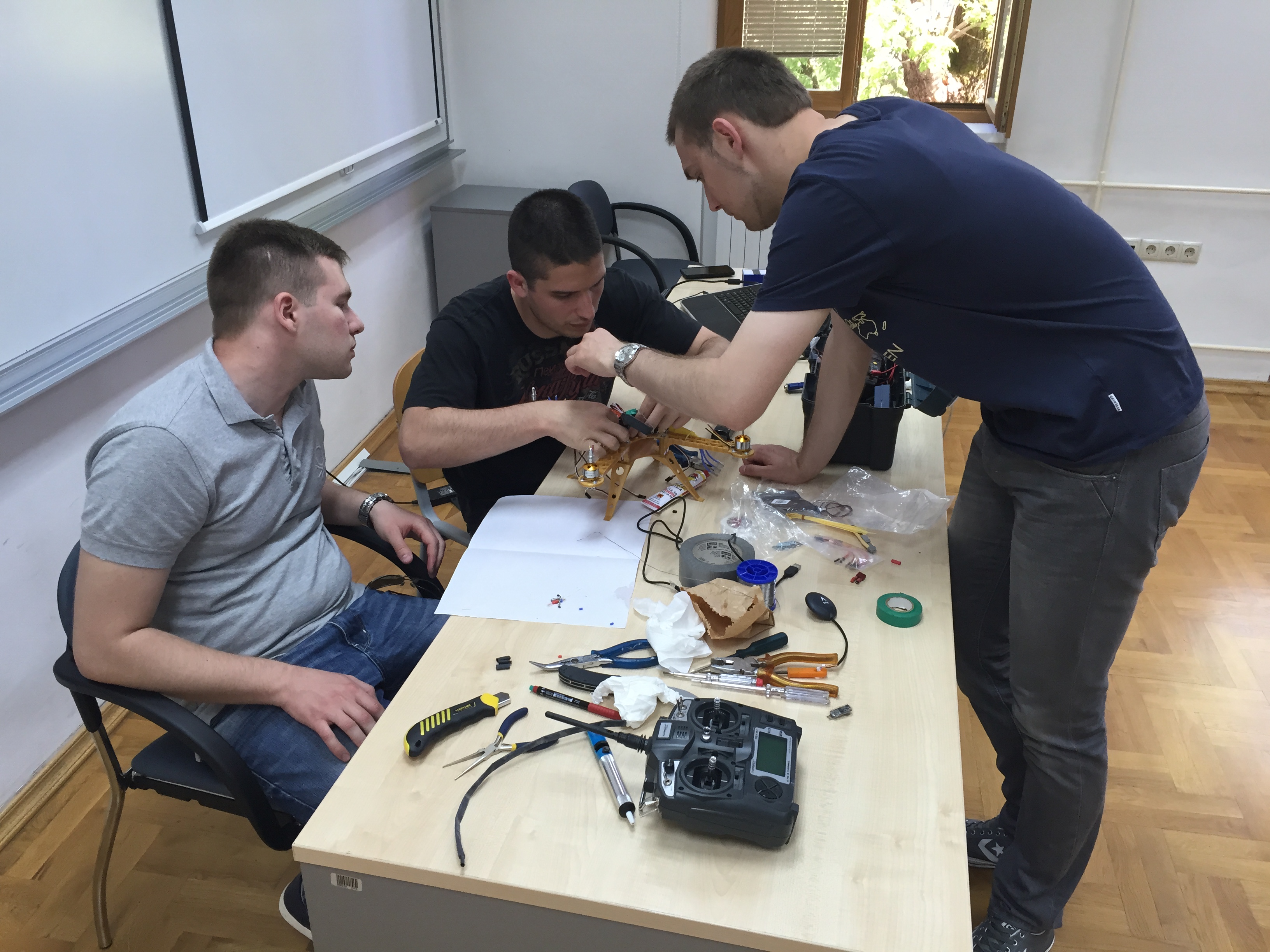
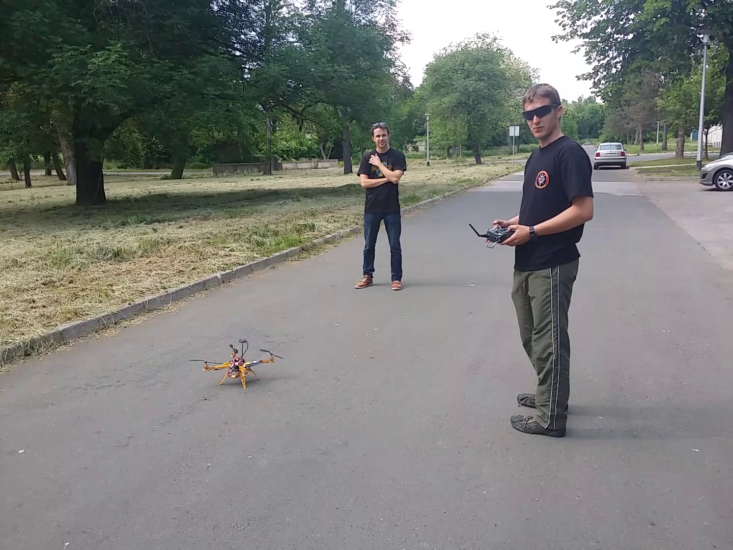
The main controller and autopilot for the quadcopter was arduino-based ArduCopter. For the radio receiver a Turnigy 9X8C-V2 8-channel receiver was used. No-name 30A electronic speed controllers were used to power the four 1000 KV outrunner motors.
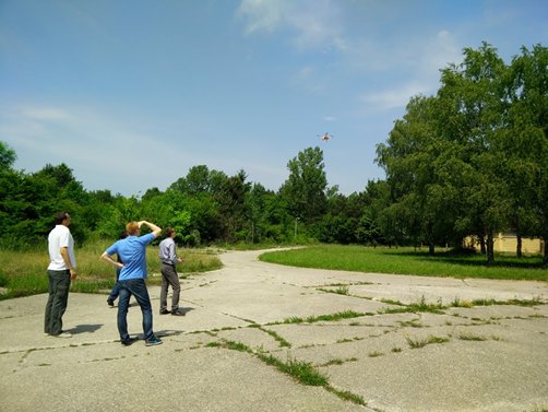
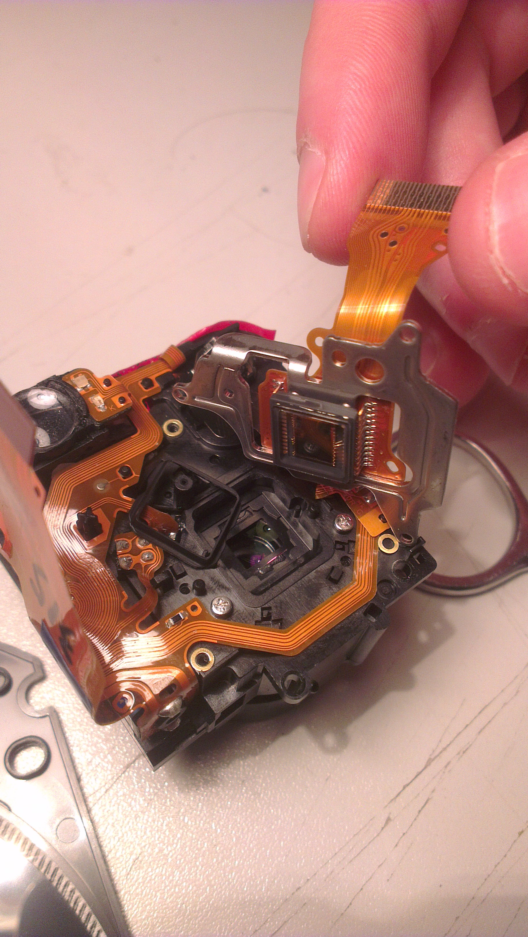
A Canon PowerShot A460 digital camera was modified to serve as an infrared sensor. The camera was disassembled and IR filter was located and replaced with an improvised visible light filter. Unfortunately, during one of the test flights IR sensor was destroyed so the project was completed using only visible light imagery.
Overall, students displayed excellent planning and designing abilities as well as resourcefulness during the construction and troubleshooting phases of the project. We hereby wish to congratulate them on all the hard work they have put into this project and success which was thus inevitable.